Compare Plastic Grid Paving Systems: The 2026 Strategic Guide
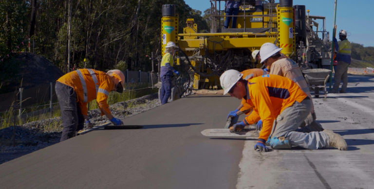
The American landscape is increasingly defined by a conflict between structural necessity and hydrological integrity. For decades, the civil engineering default was a methodology of total repulsion: sealing the earth with monolithic slabs of asphalt or concrete to shed water as rapidly as possible into municipal pipes. Compare Plastic Grid Paving Systems. However, as climatic patterns shift toward higher-intensity precipitation and urban heat island effects escalate, the “grey infrastructure” model has begun to show its terminal limitations. In its place, a sophisticated, decentralized approach has emerged, utilizing the cellular geometry of plastic grid paving to reconcile the load-bearing requirements of vehicles with the natural permeability of the earth.
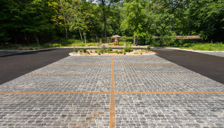
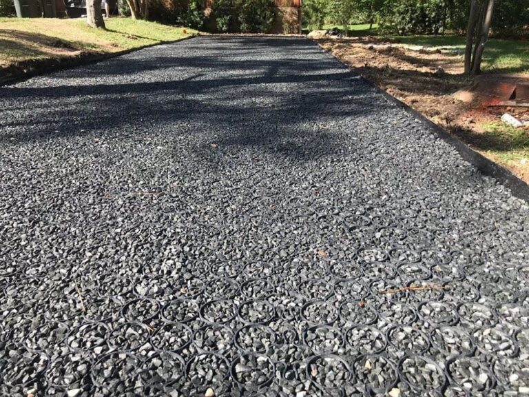
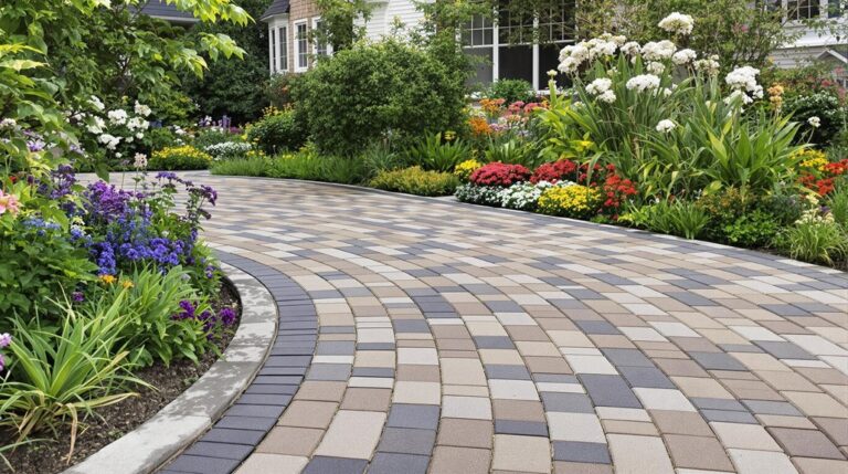
This transition from solid to cellular surfacing is not merely a change in material; it is a fundamental shift in how we conceive of the ground plane. A plastic grid is essentially a skeletal support system that “confines” an infill material—be it angular stone or living grass—preventing the lateral migration and compaction that leads to ruts and mud. In this system, the plastic provides the structural modulus, while the infill provides the infiltration capacity. It is a collaborative engineering model that treats the driveway or parking lot as a functional watershed rather than a stagnant barrier.
However, the proliferation of manufacturers and material specifications has created a complex and often confusing marketplace. To effectively analyze and navigate this sector, one must move beyond marketing claims of “high strength” and address the forensic details of polymer chemistry, interlocking mechanisms, and sub-surface reservoir dynamics. This editorial investigation serves as a pillar reference for those seeking to deploy these systems at scale, ensuring that the selection process is governed by geotechnical data rather than surface-level aesthetics.
Understanding “compare plastic grid paving systems”
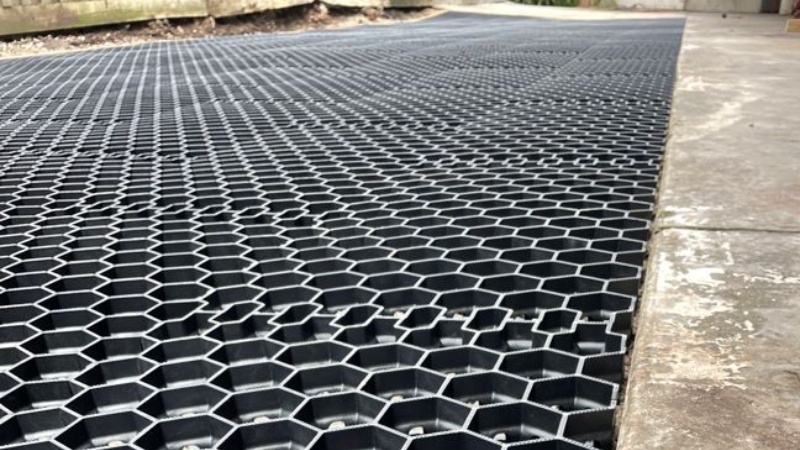
To accurately compare plastic grid paving systems, one must first dismantle the assumption that all plastic grids are interchangeable. In professional civil engineering, these systems are categorized by their “Wall Thickness,” “Cell Depth,” and “Polymer Elasticity.” A common misunderstanding among developers and institutional planners is the belief that the plastic itself carries the load. In reality, the plastic grid acts as a “Confinement Matrix.” Its primary role is to restrict the movement of the infill. When a vehicle tire passes over a cell, the angular stone within cannot move sideways; instead, the load is transferred vertically down through the stone and into the sub-base.
The risk of oversimplification often leads to a failure in “Shear Resistance.” Many lighter-duty grids designed for pedestrian paths are erroneously installed in high-torque areas, such as residential cul-de-sacs or commercial delivery bays. When a heavy vehicle turns its wheels in place on a substandard grid, the torsional force can snap the interlocking tabs or “unravel” the entire matrix. Therefore, a meaningful comparison requires a forensic look at the “Interlock Integrity”—how the individual panels connect and whether those connections can withstand the lateral stresses of a multi-point turn.
Furthermore, the comparison must extend to the “Thermal Expansion Coefficient.” High-Density Polyethylene (HDPE), the most common material in this sector, expands and contracts significantly with temperature changes. A grid installed in the heat of a Texas summer will occupy a different volume than it will during a winter freeze. Systems that lack built-in “Expansion Joints” within the panel geometry are prone to “heaving” or “buckling,” where the grid literally lifts off the sub-base as it expands, creating a tripping hazard and a structural vulnerability.
Deep Contextual Background: The Evolution of Geocells
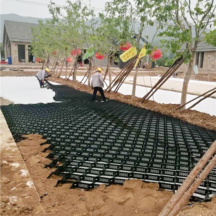
The history of plastic cellular confinement is rooted in the logistical challenges of the 20th-century military. The earliest iterations of what we now recognize as plastic grids were developed by the U.S. Army Corps of Engineers in the 1970s to facilitate the movement of heavy equipment over soft, sandy soils. These “Geocells” were essentially collapsible honeycombs that could be filled with whatever material was available on-site, providing an instant, stable roadbed.
The transition to the commercial and residential markets occurred as “Low-Impact Development” (LID) standards began to influence municipal codes. In the 1990s, European manufacturers introduced rigid, modular grids designed specifically for grass and gravel driveways. These were no longer just for “emergency” use; they were engineered as long-term alternatives to asphalt.
Today, in 2026, we have moved into the “Performance Polymer” era. We are no longer using generic plastics; we are utilizing recycled HDPE and Polypropylene blends that are UV-stabilized and reinforced with fiberglass or carbon black to prevent brittleness. This evolution reflects a maturation of our ecological understanding: the grid is no longer a niche “green” product; it is a high-performance civil engineering tool used to manage the competing demands of urbanization and environmental stewardship.
Conceptual Frameworks and Mental Models
1. The “Hoop Stress” Equilibrium
Think of each cell in a plastic grid as a tiny barrel. When you stand on the material inside the barrel, the “hoops” (the cell walls) prevent the material from bursting outward. In a paving comparison, the “best” grid is the one with the highest wall-tensile strength—the ability of the “hoops” to hold firm under extreme pressure without stretching.
2. The “Reservoir-as-Engine” Framework
This model treats the sub-base beneath the grid as a temporary storage tank. The goal of the plastic grid is to act as the “Intake Valve.” If the grid allows 90% of rain to pass through, but the sub-base is made of compacted clay, the “Engine” stalls. A meaningful comparison must look at the “Systemic Porosity”—the interaction between the grid’s open-area percentage and the sub-base’s exfiltration rate.
3. The “Elastic vs. Plastic” Deformation Scale
All paving moves. Rigid concrete is “Brittle”; it cracks when the earth moves. Asphalt is “Plastic”; it deforms (rutting). A well-engineered plastic grid is “Elastic”; it is designed to flex slightly with the seasonal movement of the soil and return to its original shape. The limit of this model is “Fatigue”—how many cycles of flexing a grid can take before the plastic “whitens” or snaps.
Key Categories: Material Physics and Engineering Trade-offs
Identifying the right system requires matching the “Grid Geometry” to the “Duty Cycle.“
| Category | Material Base | Primary Advantage | Primary Limitation |
| Rigid HDPE Grids | Recycled HDPE | High compressive strength | Low flexibility on slopes |
| Flexible Geocells | HDPE Strips (Welded) | Conforms to terrain | High labor for infill |
| Fiberglass-Reinforced | Composite | Zero thermal expansion | High initial capital cost |
| Thin-Wall Grids | Polypropylene | Maximum grass coverage | Low-torque resistance |
| Interlocking Pavers | Heavy-Wall HDPE | Superior shear strength | Lower infiltration rate |
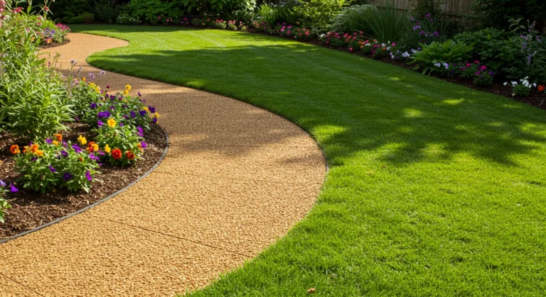
| Drivable Turf Grids | Modified PP | Hidden aesthetics | High irrigation demand |
Realistic Decision Logic
When you compare plastic grid paving systems for a high-traffic commercial lot, the decision usually favors heavy-walled, interlocking HDPE panels. The wall thickness (typically 3mm to 5mm) provides a “safety factor” against the aggressive braking of delivery trucks. Conversely, for a residential overflow parking area that prioritizes “green space,” a thin-walled, flexible system allows for more soil volume, which is essential for the long-term health of the grass root-zone.
Detailed Real-World Scenarios Compare Plastic Grid Paving Systems
Scenario A: The Pacific Northwest Slope
-
Constraint: A 12% grade driveway in a region with 50 inches of annual rainfall.
-
The Strategic Choice: Utilizing a “Flexible Geocell” system rather than rigid panels. The flexible strips allow for “terracing” within the sub-base, preventing the stone infill from washing out the bottom of the hill.
-
Failure Mode: A rigid panel system on a 12% slope often creates a “slide plane” where the entire grid can shift downhill if not anchored with expensive rebar “J-hooks.”
Scenario B: The Southwest Arid Parking Lot
-
Constraint: High UV exposure and extreme heat (110°F+).
-
The Strategic Choice: Carbon-black stabilized HDPE grids with a “Crushed Granite” infill.
-
Second-Order Effect: The carbon black prevents UV-induced brittleness, while the open-stone infill prevents the “Heat Island” effect, lowering the ambient temperature of the parking lot by 20 degrees compared to the adjacent asphalt road.
Planning, Cost, and Resource Dynamics
The economic profile of plastic grid paving is characterized by “Front-Loaded Labor” but “Minimal Long-term Infrastructure.”
| Expense Component | Standard Asphalt | High-End Plastic Grid | Variability Factor |
| Excavation | 6-8 inches | 10-14 inches | Soil “Perc” rate |
| Base Material | Dense-graded ($) | Open-graded ($$$) | Local quarry distance |
| Product Cost | $ | $$$ | Material virgin vs. recycled |
| Secondary Drainage | $$$ (Pipes/Ponds) | $ (Eliminated) | Municipal LID credits |
| Lifecycle | 12-15 years | 25+ years | Maintenance adherence |
The Opportunity Cost: In many American urban infill projects, the “cost” of the plastic grid is effectively zero because it allows the developer to eliminate a surface-level detention pond. The 500 square feet of land reclaimed from that pond can be used for an extra parking space or a larger building footprint, often worth $50,000 to $100,000 in high-value markets.
Tools, Strategies, and Technical Support Systems
To execute at the highest tier of hardscaping, the following technical support systems are required:
-
Double-Ring Infiltrometer: Verification of the sub-grade’s ability to “drink” the water.
-
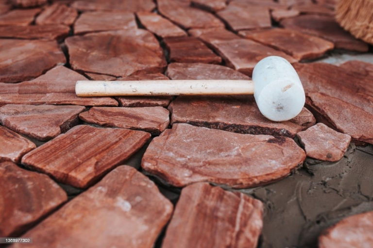
Angular Stone Spec (#57 or #8): Round “pea gravel” is the enemy of plastic grids; it acts like ball bearings and allows the grid to shift. Angular stone “locks” into the cells.
-
Non-Woven Geotextiles: These act as the “Separation Layer,” preventing the clean stone base from being “poisoned” by the migration of native clay or mud.
-
Plate Compaction Protocols: Grids must be compacted after infill to “seat” the stone into the cells, creating the mechanical interlock.
-
Smart Anchoring: In high-slope or high-torque zones, the use of helical anchors or Duckbill anchors is mandatory to prevent horizontal “creep.”
-
Edge Restraints: Rigid aluminum or heavy-duty plastic edging is required to prevent the “unravelling” of the perimeter cells.
Risk Landscape and Taxonomy of Failure Modes
-
“Blinding” (Biological Clogging): This is the most common failure. It occurs when grass clippings, mulch, or silt wash onto the surface and rot, creating a waterproof “skin” over the cells.
-
Structural Subsidence: This happens when the reservoir is not “vented” or provided with an overflow pipe. The sub-grade stays saturated for too long, softens, and the entire driveway sinks.
-
“Pop-Outs”: Caused by the use of rounded stone. Under the pressure of a tire, the round stone “pops” out of the cell like a bar of soap, leaving the plastic wall exposed to UV damage and crushing.
-
Interlock Shear: The breaking of the connection tabs between panels. This usually happens because the sub-base was not perfectly level, causing one panel to sit higher than the other and taking the brunt of the vehicle’s lateral force.
Governance, Maintenance, and Long-Term Adaptation
A plastic grid system is a “Managed Asset,” not a “Set-and-Forget” slab.
The Stewardship Checklist
-
Quarterly Visual Audit: Looking for “Settlement.” If the stone infill has dropped more than 1/2 inch below the plastic wall, it must be “recharged” with more stone to protect the plastic from UV exposure and tire crushing.
-
Annual “Deep Vacuuming”: For stone-filled systems, using a regenerative air sweeper to pull out the fine silt that settles in the pores.
-
Mowing Height Governance: For grass systems, the mower must be set to 3+ inches. If the grass is scalped, the “Crown” is exposed to tire damage, leading to “biological failure.”
Measurement, Tracking, and Evaluation
How do we prove the system is performing? We move from “It looks dry” to quantitative data.
-
Infiltration Rate ($I_{rate}$): A new system should process 100+ inches per hour. If it drops below 10 inches, “Regenerative Maintenance” is mandatory.
-
TSS (Total Suspended Solids) Capture: Measuring the amount of sediment trapped in the aggregate. This is a “Leading Indicator” of system health.
-
Void Ratio Persistence: Checking if the stone infill has “compacted” to the point where it no longer holds water.
Common Misconceptions and Ethical Considerations
-
Myth: “It’s just cheap plastic.” Correction: High-performance grids are engineered polymers designed to last 50 years underground; they are more durable than asphalt in many climates.
-
Myth: “You can’t plow it.” Correction: You can plow it with a “Rubber-Edged Blade.” A steel blade will catch the plastic walls and tear the system apart.
-
Myth: “It breeds mosquitoes.” Correction: Properly designed systems drain in less than 2 hours; mosquitoes require 7 days of standing water to hatch.
Ethical Consideration: By choosing to compare plastic grid paving systems and install an infiltration-based hardscape, a property owner is essentially “donating” their land’s natural hydrological function back to the community. This reduces the “Social Cost” of flooding and helps prevent the “Urban Heat Island” effect that disproportionately affects lower-income neighborhoods.
Conclusion: The Architecture of Resilience
The trajectory of American hardscaping is moving away from the “Brute Force” engineering of the 20th century toward the “Collaborative Engineering” of the 21st. The plastic grid is the primary tool in this transition. It represents a maturation of our relationship with the earth—an acknowledgment that we can have the strength of a road and the health of a watershed in the same square foot.
As we look toward the 2030s, the “Impenetrable Slab” will be viewed as a historical anomaly—a brief period where we believed we could ignore the physics of water. The surfaces that endure will be those that were built with the understanding that the ground is a living, breathing system. By designing for infiltration, we create a built environment that is not only structurally sovereign but ecologically restorative.